Automatic extinguishing control panel
POLON 4500

Overview
The POLON 4500 fire extinguishing system control unit is designed for fire detection and actuation and operation monitoring of automatic fire extinguishing systems. It is intended for control of maximum 4 extinguishing zones.
Fire detection
The POLON 4500 control unit is a multi -processor one, with two processor circuits (redundancy). In case of the control unit main processor damage, its functions are taken over by the second one, without any break in the system operation. A basic version of the control unit is equipped with four addressable detector loops, enabling connection (and addressing) of 127 line elements in each loop. The POLON 4500 control unit can interoperate with the POLON 4500 and the POLON 4900 control panels in hierarchical ring structure. The detector lines can operate as loops or as open detection lines. In case of a detector loop, it is possible to eliminate the damages caused by a short circuit or a brake in a part of the detector line. Ability to control and signal an excess of the allowable detector line wire resistance and capacity values is a novelty in this design. When the installation is designed, it is a possibility to create branch lines from the main detector loop, what makes the installation of wires easier. Addressable elements of each control panel can be program assigned to 512 zones and described with user messages, consisting of two rows, 32-character text each. In case of an alarm, the proper information is given on a large liquid crystal display, enabling fast and precise location of the fire source. Additionally, there is a possibility of programming own notifications for the so-called technical alarms related to the control of the fire protection automatics monitored by the control panel. A large graphic display and developed window menu (similar to the PC operation system) makes service and communication with the control panel much easier.
Entering the configuration of the fire alarm installation into the memory of the control panel can be done in three ways:
- automatic configuration – when the control panel checks itself where the line elements are installed in each detectorloop (even in case of a loop with single branches). On this basis, all the data are saved in the control panel memory and address (number) of every line element is entered and saved in its own internal memory,
- installer configuration – in this option, an installer (relying on the data described in the installation design) prepares a system configuration as a computer file, using the special software, delivered by the manufacturer. Then the configuration is transferred to the control panel memory. All these function can be done using only a computer keyboard, connected to the proper input in the control panel. Entered data are then verified (the fitter’s configuration is compared with the factual state by reading of the line elements memory). If the factual state is corresponding with the fitter’s configuration data, the line elements will automatically be numbered,
- manual configuration – enables to freely configure the line elements without the necessity of watching for numbering of the elements. It makes it possible to introduce changes into the installation (e.g. after replacing some detectors). This operation can be done much faster by using a bar code reader connected to the control panel.
After updating a detector or a manual call point in an addressable detector loop, the POLON 4500 control unit, using decision algorithms, activates the pre- or main fire alarm, depending on the programmed alarm variant or on line element that was actuated.
It is possible (at the POLON 4500 control unit level) to program the choice of one of 17 alarm variants for each zone. Different alarm variants, related to different detection algorithms, enable optimal usage of the fire alarm system in individual conditions existing in a particular zone. They allow, also, for introducing individual criteria for efficient organization of a given object protection system. Additionally, there is a possibility to divide the line elements in one zone into two groups, what enables to create a coincidence in this zone.
Available alarm variants:
- normal, single and double-stage,
- alarm with single reset of 40/60 element single and doublestage,
- alarm with single reset of 60/480 element single and doublestage,
- alarm with double-detector coincidence, single and doublestage,
- alarm with group-time coincidence, single and double-stage,
- single and double-stage interactive alarm
- two-stage alarm with time-group interdependence,
- one-stage alarm in a „Personnel absent” mode of operation.
The POLON 4500 control unit can control the signalling and fire-fighting equipment using two built-in groups of control outputs. These are 8 relay outputs with potential free, change-over contacts, and 4 supervised monitoring lines. The control panel outputs can be program bound to optional zone or zone groups in 6 operation categories and in numerous variants in one category. Four supervised control lines enable to supervise the state of connected external devices or circuits.
Serial outputs (RS 232 and RS 485, USB, PS/2) enable con-nection of a computer keyboard, a computer, a bar code reader, a digital monitoring system, integration and system controlling equipment to the control panel, as well as combining of the control panels in a network structure.
The POLON 4500 control unit remembers 2,000 latest occurrences, which took place during monitoring of the premises and a maximum of 9,999 alarms. The record of these events can be printed out on a paper tape in order according to the date and time of the occurrence with a built-in thermal printer, or may be shown on the control panel display.
Control of extinguishing process
The POLON 4500 control unit can be equipped with 1, 2, 3, or 4 MSG-45 modules, intended for controlling the automatic extinguishing process in a maximum of 4 extinguishing zones. Each module is equipped with 16 control relays and 11 supervising inputs, designated for connection of external monitoring and controlling lines.
The supervising line contacts are designed for connection of the EXTINGUISHING, STOP, EXTINGUISHING BLOCKADE push buttons and for supervising of extinguishing installation conditions. Each supervising line can represent one of four following conditions:
- fault condition (short-circuit),
- active condition (alarm),
- quiescent condition,
- damage condition (break in line)
Automatic extinguishing procedure is activated when:
- a fire is detected by at least two detectors operating in two detector or group coincidence, which are installed in the same extinguishing zone (an automatic mode),
- a manual triggering device (EXTINGUISHING push button) is activated (manual mode)
The activated condition is signalised by optical and acoustic devices.
In addition, the control unit is able to signal the following conditions of extinguishing installation:
- released condition,
- fault condition of the MSG-45 module,
- disabled condition (of supervising line, relay),
- the optical signalling device and the monitoring lines of the MSG-45 module test status.
Design
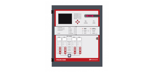
The POLON 4500 fi re exti nguishing systems control unit is made in a form of a cabinet, which can be fastened to the wall. The cabinet has a door, carrying signalling and handling elements, which is closed with a cylinder lock.
A large liquid crystal display is placed at the left top part of the door. In the middle, there are the control panel main service elements – a keyboard and LED diodes, informing of the present state of the fire alarm system.
There is a slot in the bottom part of the door – an output of the printer paper tape.
The main electronic circuits, having a form of modules, are mounted on the interior side of the door and on the rear wall of the control panel.
Two reserve batteries - 2 x 12 V with a capacity of at least 38 Ah can be connected as a secondary power supply source. The batteries, having a capacity of up to 44 Ah are installed inside a PAR-4800 battery container. Batteries having more than 44 Ah (up to max.180 Ah) have to be installed outside of the control unit in an additional PAR-4800 container.
| TECHNICAL DATA | |
|---|---|
| Number of potential-free relay outputs | 9 |
| Number of potential outputs | 7 |
| Number of monitoring inputs | 11 |
| Supply voltage: main | 230V |
| Supply voltage: standby | 2pcs. 12V 38Ah to 180Ah |
| Max. quiescent current consumption | 0.05A |
| Numer of alarming variants | 17 |
| Signaling lines (potential) | 4 |
| Number of detectors in line | 127 |
| Detection line isolation resistance | or more |
| Relay outputs | potential free in control panle 8 load 1A 30V |
| Number of detection lines | 4 |
| Number of extinguishing zones | 1 |
| Number of monitoring lines | 4 |
| Number of detection zones | 1024 |
| Operating temperature range | from -5°C to 40°C |
| Dimensions (mm) | 314x368x106 |
